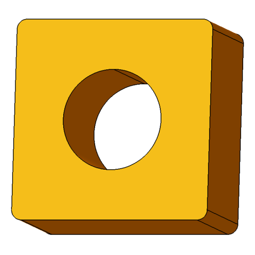
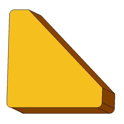
Left
Right
Front
Back
Bottom
Top

Info: Description

    • Animate
    • Animate:
    360-degree view animation
    • Wireframe
    • Wireframe:
    Displays only model edges.
    • Shading without edges
    • Shading without edges:
    Displays only surfaces.
    • Shading with edges
    • Shading with edges:
    Displays the entire model.

    • Zoom -
    • Zoom -:
    Zooms out the view.
    • Zoom +
    • Zoom +:
    Zooms in the view.
    • Measure
    • Measure:
    Measures from and between elements.
    • Section View
    • Section View:
    Creates a section in the view.

    • Screenshot
    • Screenshot:
    Downloads a screenshot.

Modeling:

Info: Description

    • Drilling
    • Drilling:
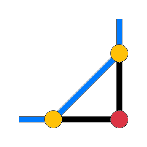
    Insert holes, threads, and countersinks at sketch points.
    • Bevel Cut
    • Bevel Cut:
    For bevel cut, select plane, angle, and width.

Shapes:

Info: Description

    • New
    • New:
    Clears the content of the sketch.
    • DXF Upload
    • DXF Upload:
    Opens a dialog for uploading a DXF file.
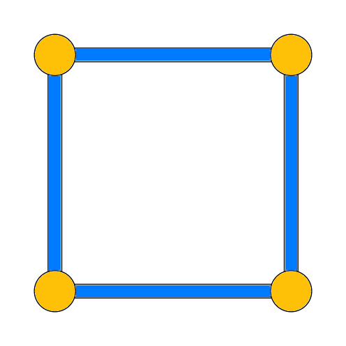
    • Rectangle
    • Rectangle:
    Creates a rectangle using two points.
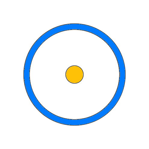
    • Circle
    • Circle:
    Creates a full circle with a start point and radius.
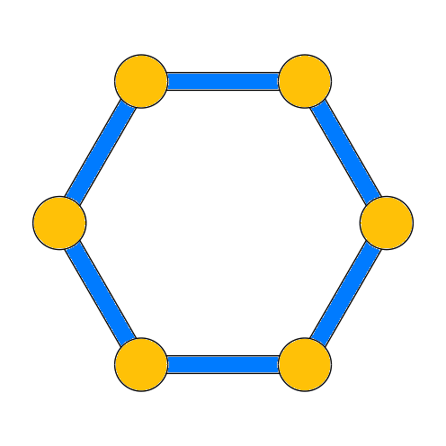
    • Hexagon
    • Hexagon:
    Creates a hexagon using the center and outer point.
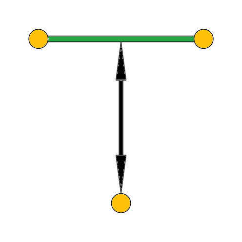
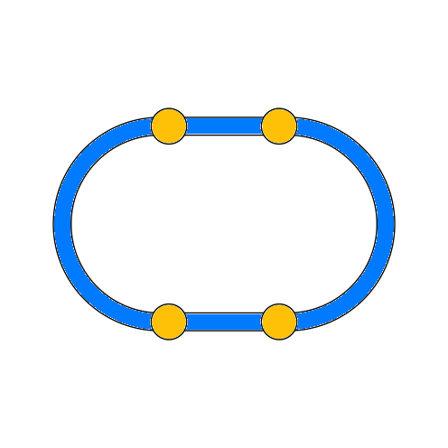
    • Long Hole
    • Long Hole:
    Inserts a long hole shape using the center points of the circular arcs.
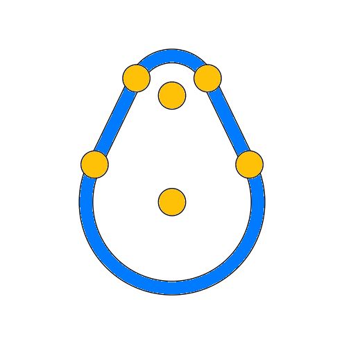
    • Cam
    • Cam:
    Draws a cam using the center points of circular arcs with different radii.
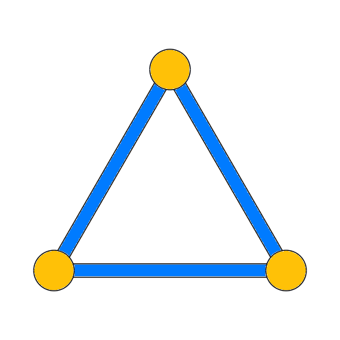
    • Triangle
    • Triangle:
    Creates a triangle.
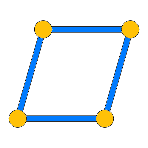
    • Parallelogram
    • Parallelogram:
    Creates a parallelogram with an inclination angle.
    • Trapezoid
    • Trapezoid:
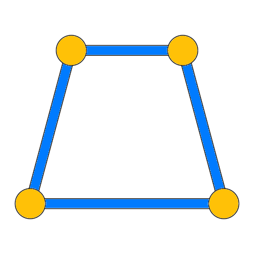
    Creates a trapezoid with two inclination angles.

Segments:

Info: Description

    • Point
    • Point:
    Inserts a point into the sketch.
    • Line
    • Line:
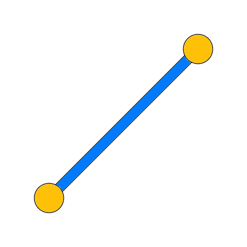
    Creates a line with two endpoints.
    • Polyline
    • Polyline:
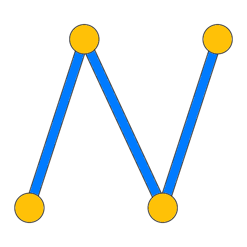
    Creates a polyline that can be closed. Click on an existing point to finish the process.
    • Arc
    • Arc:
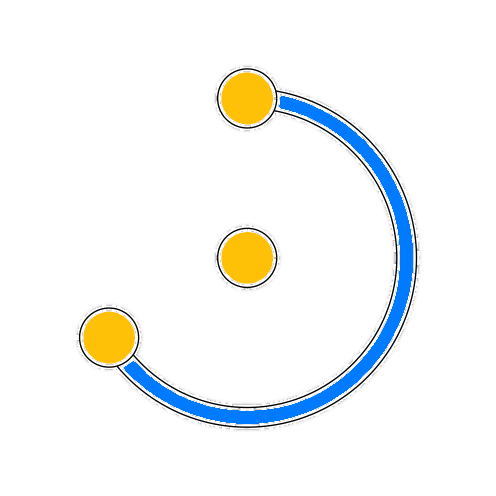
    Creates a partial circle from three points with a radius.

Modify:

Info: Description

    • Chamfer
    • Chamfer:
    Inserts a line at the selected corner point and trims adjacent elements.
    • Rounding
    • Rounding:
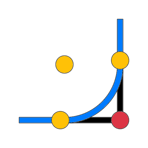
    desc-modify-rounding
    • designElement
    • designElement:
    Changes the element status between construction and auxiliary element. Auxiliary elements are not considered in volume generation.
    • Trim
    • Trim:
    Trimming removes segments from the sketch. Activate the mode and select one or more segments to be deleted in the sketch.

Constraints:

Info: Description

    • Fixation
    • Fixation:
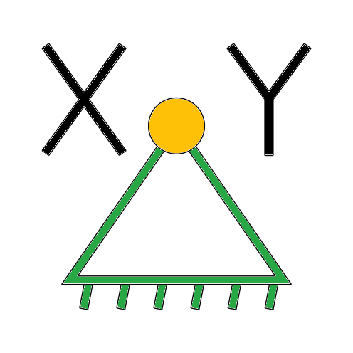
    Creates an X-Y coordinate position at points.
    • Element Dimension
    • Element Dimension:
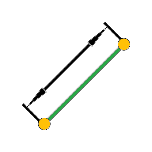
    Creates a dimension for an element.
    • Offset
    • Offset:
    Defines the distance between two elements.
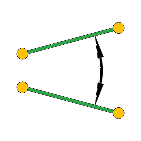
    • Angle
    • Angle:
    Sets an angle between two lines.
    • Congruence
    • Congruence:
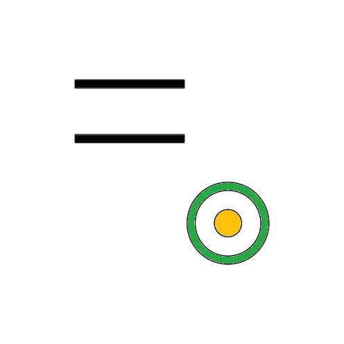
    Overlays two points, making them identical.
    • Horizontal
    • Horizontal:
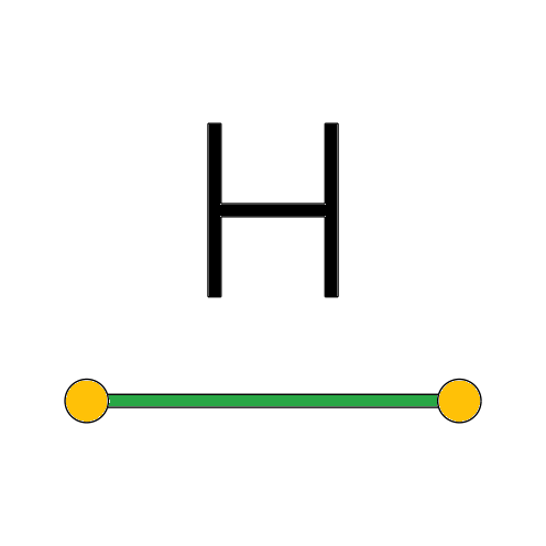
    Defines lines in the horizontal direction.
    • Vertical
    • Vertical:
    Defines lines in the vertical direction.
    • Tangential
    • Tangential:
    Positions circles and lines with a tangent condition.
    • Orthogonal
    • Orthogonal:
    Sets two lines perpendicular to each other.

Profiles

Part Properties:

Variant:
Depth:
min: 10 mm, max: 2000 mm

Info: Part Properties

Enter a name for the part that best reflects its properties.

The description helps you to better find your part later and understand the purpose of the design.

Configure the desired material of the part, surface coating, or hardening.

Operations:

Info: Operations

This is a list of all 3D operations on the part. Here you can change, edit, or delete the name, color of the respective surfaces. By moving the mouse over the part, you can trace the history of the component.

Description:

Manufacturing Process:

We cut profiles on a modern band saw. Customers can easily configure miter cuts in the desired plane. Drilling represents a post-processing operation on the workpiece, carried out with a conventional drill press.

Properties:

  • Tolerance on the cut length +/- 1.0 mm, unless otherwise specified (see Distance Tolerance tab).
  • The dimensions and wall thicknesses of the profiles correspond to the applicable standard and manufacturer tolerances of the semi-finished material used.
  • Cut surfaces may show slight grooves or other machining marks due to the process.
  • profilesProperties4
  • Cut edges are deburred. An additional chamfer is only made if specified.
  • Miter cuts and deviating cutting angles can be produced according to the component geometry.
  • Steel profiles may show surface characteristics caused by rolling, storage, and transport, such as scale, light scratches, or discoloration.
  • Dimensions are always given in millimeters.

Tutorial:

Profile cuts are created based on a selected steel profile. Using the -Modeling- group tabs, the profile type, cross-section, length, and cutting angle can be defined. The component can then be extended with further specifications.

Straight cuts, miter cuts, and further processing can be defined via the corresponding tabs. Cut dimensions and additional requirements can be edited or deleted at any time.

Sketcher
Sketcher

Align:

Info: Description

The sketch can be oriented along a coordinate axis or centrally using the direction arrows.

Transform Origin:

Info: Description

Incremental shifting or rotation of the local coordinate system. The change affects the entire sketch position.

Elements:

Info: Description

List of all elements in the sketch.

Rectangular pattern:

∆ x:
∆ y:
num x:
num y:

Info: Rectangular pattern

On the left side, the Pattern action can be executed. The values stored in the input fields are taken into account.

On the right side of the dialog, the shape of the pattern can be defined in terms of horizontal number, vertical number, and horizontal distance, vertical distance.

Circular pattern:

x:
y:
Winkel:
num:

Info: Circular pattern

Clicking the button applies the values in the dialog to the sketch.

In the input fields, a point in X and Y can be specified around which the sketch should be rotated. Then, an intermediate angle and the desired number of copies must be specified.

Description:

The sketcher is used to create 2D geometries as a basis for various modeling operations in 3D space. Besides the quick selection for basic shapes, you can create, modify, and delete your own paths with segments. Constraints are small mathematical formulas that are attached to objects upon selection to define the position and alignment precisely. The constraints can remain throughout the entire design process.
Material0mm
Width0mm
Height0mm
Depth0mm
Radius0mm
Diameter0mm
Length0mm
Thread0
    • Weight:
    • 0 kg
    • Delivery time:
    • 0 Working days
    • Net price:
    • 0 €
    • additional parts each:
    • 0 €
    • inlcuding VAT:
    • 0 %
    • Gross price:
    • 0 €
    • Quantity:

Wir Nutzen Cookies damit diese Seite funktioniert:

Yes, I have read the privacy policy und AGB and acknowledge it.