Left
Right
Front
Back
Bottom
Top
Info: Description

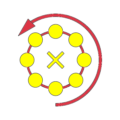
Animate:
360-degree view animation
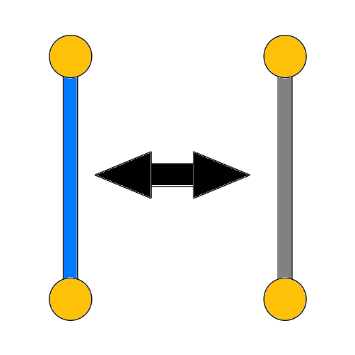
Wireframe:
Displays only model edges.
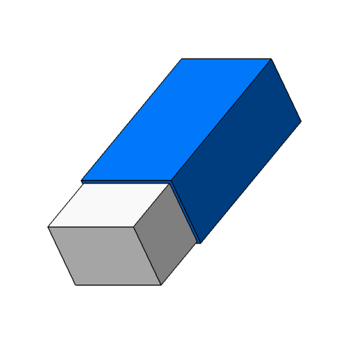
Shading without edges:
Displays only surfaces.
Shading with edges:
Displays the entire model.
Zoom -:
Zooms out the view.
Zoom +:
Zooms in the view.
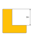
Measure:
Measures from and between elements.
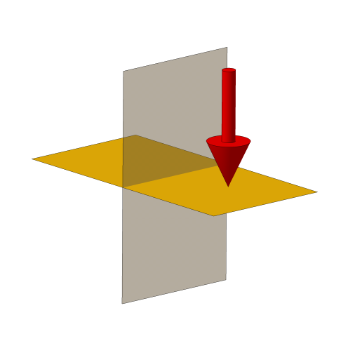
Section View:
Creates a section in the view.
Screenshot:
Downloads a screenshot.